This space is a device Red Green and Blue colorspace, where the conversion from measured, device independent values to device dependent RGB values can be configured.
Most often this would be used to set the Reference Measurement
value in terms of a desired device value, so that a device like a
Video Display or TV can be measured and adjusted to minimize the
difference (Delta) to the desired reference color. Combining this
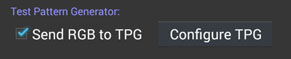
with Send RGB to TPG option is a convenient
way of measuring and comparing to a specific reference color.
Note that the values displayed or entered are not constrained to
the limited device range, although out of range values will be
displayed in RED. Values sent to the
TPG will always be clipped to the device range.
There are seven parts to the configuration of the RGB device
model:
Three primary colors plus white define the fundamental colors
that are mixed together by the display, and the balance between
them when they are all 100%.
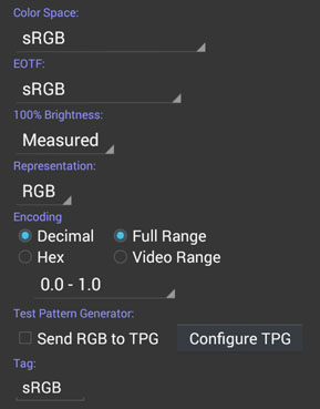
There is a pull down list to choose between standard RGB encoding
colorspaces:
| |
sRGB | Standard for computer display and the Web |
| AdobeRGB1998 | Photographic and graphic arts standard | |
| ProPhoto RGB | Wide gamut photographic space | |
| PAL/EBU 3212 | Standard definition European TV | |
| NTSC/SMPTE RP 145 |
Standard definition USA TV | |
| ITU-R BT.709 | High Definition TV |
|
| ITU-R BT.2020 | UHD TV | |
| DCI-P3/SMPTE-431-2 |
Digital Cinema |
Plus two ways of specifying custom primaries:
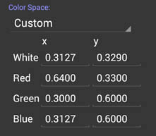
| |
Measured |
Where the measurement values of the R,G,B & White Primary Color References are used. |
| Custom | Where the R,G,B & White x & y Chromaticity coordinates can be specified manually. |
The EOTF determines how the light produced in each of the R,G
& B channels responds to the device value. Typically it will
be power like curve, often called a "Gamma" curve. Standard
encoding colorspaces have a standard EOTF, and by default this
corresponding EOTF will be chosen when you select a standard
colorspace. This will be the first entry in the EOTF pull down
list.
For a Measured or Custom set of primaries there is no standard
EOTF, so one must be specified, and for some purposes (such as
display calibration) it usually desirable to use a specific
display or decoding EOTF rather than the one used by the encoding
space standard.
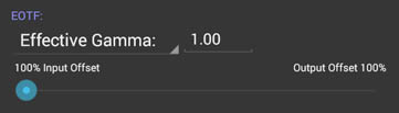
There are three choices for this:
| |
BT.1886 | Reference EOTF with a technical gamma (power function) of 2.4 and an input black offset strategy |
| |
Effective Gamma |
Configurable gamma that is such that the 50%
output value has the chosen power, irrespective of any black
offse, and that then has the black offset strategy applied
to it. |
| |
Technical Gamma |
Configurable gamma (power function) value that then has the black offset strategy applied to it |
Real world display don't have a perfect zero black, so some
strategy is needed to fit the EOTF so that it matches the display
black point at zero. (Encoding spaces don't make any allowance for
this, and assume a perfect zero black). The black level is assumed
to be measured and stored in the Black Primary
Color Reference.
There are two basic
strategies: Input black offset or Output black offset.
Input black offset
scales and offsets the gamma curve so that zero device value
mapped through the curve gives the black point of the display.
This has the benefit of preserving shadow detail just above
black. It has the disadvantage of sometimes over emphasizing
shadow detail at the expense of contrast.
Output black offset
scales and offsets the gamma curve so that the zero input and
output point of the curve maps to the black point of the
display. This is sometimes referred to as a "pure gamma
curve", even though it is not pure. It has the advantage of
preserving maximum contrast ratio, but can result in loss of
shadow detail.
The configuration
offers a choice of input or output offset with a slider,
allowing a hybrid of the two to be chosen.
Note that the Black
Primary Color Reference can be manually set to zero by
configuring a readout to show the Black Reference, and then
setting the value (double tap).
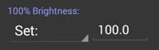
While the primaries and white chosen determine the color and
relative brightness of a device RGB value, the absolute brightness
of white is determined separately. There are two choices:
| |
Measured |
Where the measurement values White Primary Color Reference Y value is used. |
| Set | Where
the brightness can be set numerically. |
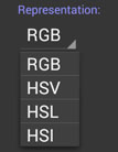
The readout value can be set to show the native RGB values, or
several alternate representations. These alternates are simple
transformations of the RGB values, intended to correspond to the
view of color being composed of a Hue angle, a Color intensity
number called Chroma or Saturation, and some sort of number
representing the distance from black to white along the neutral
axis named Value, Lightness or Intensity, depending on the
particular model.
While all these representations were intended to be more
intuitively understandable than RGB, in practice their naive
Luminance values and the distortions necessary to map all of the
device dependent RGB colorspace to/from these spaces without any
gaps, makes them highly visually non-uniform and hence hard to
use. They are provided here for easy comparison or translation to
other systems that use these representations.
If any Representation other than RGB is chosen, then the encoding
is always 0..360° for H, and 0..100% for Saturation, Value,
Lightness and Intensity.
| |
RGB |
Red, Green Blue |
Native Representation |
| HSV |
Hue Saturation Value |
V=100% for Saturated colors |
|
| HSL |
Hue Saturation Lightness |
L=50% for Saturated colors |
|
| HSI | Hue Saturation Intensity |
I=33.3% for Saturated colors |
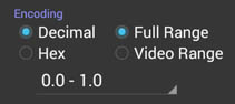
The final part of the configuration is determining what scale and
number base to display the RGB in.
(Number Encoding is not available if an HSV, HSL or HSI
Representation is selected.)
| |
Decimal |
Hexadecimal | |
| 0.0 - 1.0 | |||
| 0.0 - 100 % |
|||
| 8 bit | 0 - 255 | 0 - ff | |
| 10 bit |
0-1203 | 0 - 3ff | |
| 12 bit |
0-4095 | 0 - fff |
There is also an independent choice of whether the numbers are
over their full range where 0 is black and maximum is white, or
whether the restricted Video range is used, where 8 bit value 16
corresponds the Black, and value 235 corresponds to White.
The last entry is a text Tag name, used to distinguish the
Readout. By default it will be a short version of the primaries
color space, but can be overridden to add any other important
distinguisher. The default can be restored by deleting the tag
text.
